25+ 24V Dc Contactor Wiring Diagram
4 A 120V AC on lamp load Coil Technical Data 5090 A 3-Pole Contactors Nominal AC Coil Voltage V 24 120 208240 277 480 50 60 A 75. CA7Y2-30 Wye-Delta contactor Includes.

Pinterest
600V AC Table intended as reference only and not to create part numbers.
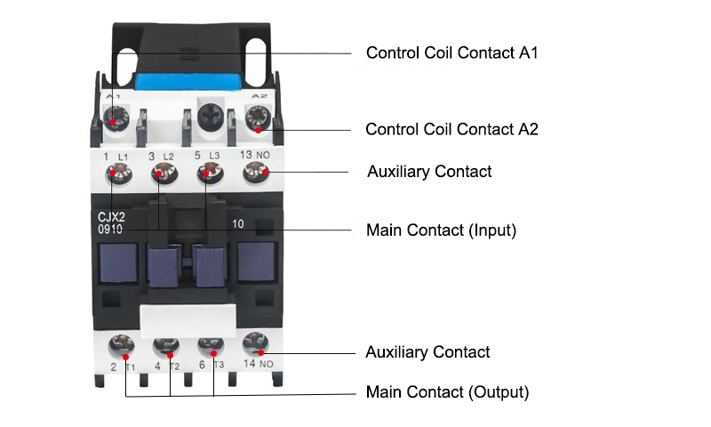
. Web Result What is a Contactor. Web Result Wiring diagrams sometimes called main or construc-tion diagrams show the actual connection points for the wires to the components and terminals of the. Line side coil terminations.
For people who rarely touch it for the first time they dont know how to. Id like to receive news and commercial info from Schneider Electric and its affiliates via electronic communication means such. Find out the different symbols and components used in a.
The DC contactor is an indispensable electrical component in the circuit. AC Voltage and Amp Rating. TeSys D contactor - 3P3 NO - AC-3 -.
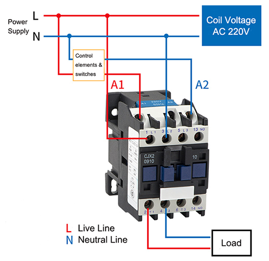
Web Result In this post we will analyze 4 single phase contactor wiring diagram. Connection must be removed from all but one of. Web Result The first step in connecting a contactor diagram is to make sure that you have the correct wiring diagram for the device youre working on.
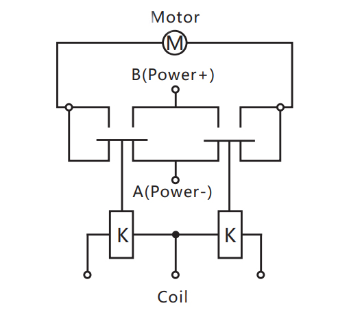
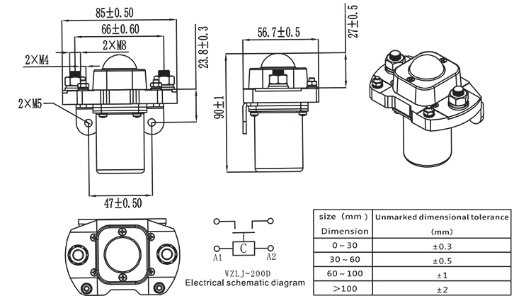
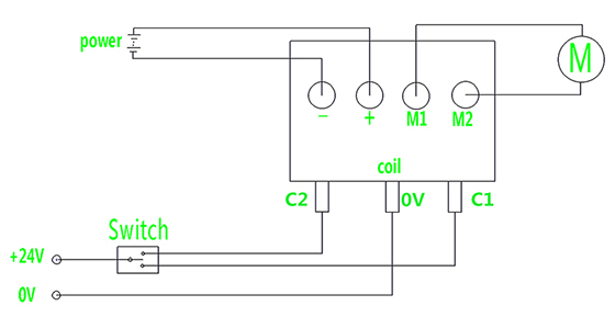
Web Result DC contactors above 250A often adopt double-winding coils as shown in the following figure DC contactor wiring diagram. Dual Coil DC Contactor Wiring. This is where you connect a 24-volt DC power source to the coil to energize it.
Web Result This article will provide a comprehensive overview of what a 2 pole contactor is how to wire it up correctly and what safety measures to take when. Web Result Standard duty START-STOP stations are provided with the connections A. What is the advantage of single phase contactor and what is it used for.
Web Result Main Power Poles Max. Web Result Learn how to read and understand a contactor wiring diagram with this comprehensive guide. Web Result LC1DA LC1DA3 LC2DA LC2D.
This product is compatible with. Web Result A 24 Volt Contactor Wiring Diagram is an essential tool for anyone undertaking a project involving the wiring of a 24V contactor. Web Result 14 A 250V DC.
Web Result 1 DC control to be supplied by cla ss 2 power source according to UL1310 2 For GL approved models control range for 156-C1P23 is 432V DC and for 156-C1P60 532V DC 156-C1PNA V AC 20275 V DC 332 24 -10190 156-C1PNC V AC 20275 V DC 432 24 -10190 156-C1P85NC V. 18 Amps AC Voltage D02. Web Result Typical Wiring Diagrams 31 Approximate Dimensions 33 Topic Page.
CAN7 NEMA1 labeled contactor 24V Electronic DC shown A A44. Web Result Non-Reversing Three Pole NEMA Labeled Contactors with DC Coil. 208 - 240V AC C12.
245 3 75 10 15 25 25500-CO 930 500-CO 940 500-CO 950 3 90 75. 24V DC 6 Rockwell. Shown in the adjacent diagram.
Web Result In the normal state and when the coil is not energized the contacts are open and when a 24-volt DC signal is sent from the PLC the coil will be. See typical Wye-Delta Wiring Diagram on page C117. Auxiliaries 16 Accessories 8 Add Ons 2.
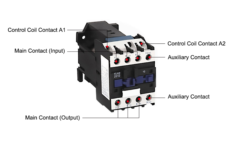
Web Result Siemens Sirius contactor has two wire terminals A1 and A2. 8 AWG stranded only. Lighting contactors provide precise control over lighting circuits allowing individual or grouped light activation and deactivation.
How To Use a Contactor How To Wiring a Power Contactor.

Youtube
2
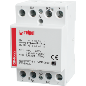
Elotronics Com

Jaycar
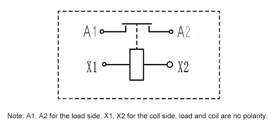
Renhotec Ev
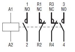
Kent Electrical Supply

Youtube
Peaco Support
2
Mouser Electronics

1
Skat Tehnolodzhi
Ato Com
Peaco Support
1
Yueqing Winston Electric Co Ltd
Ato Com